My Aerial History, From Hugh, M0DSZ
My first aerial was an inverted-L about 46m long and 10m high. This gave good results with a generous number of DX contacts.
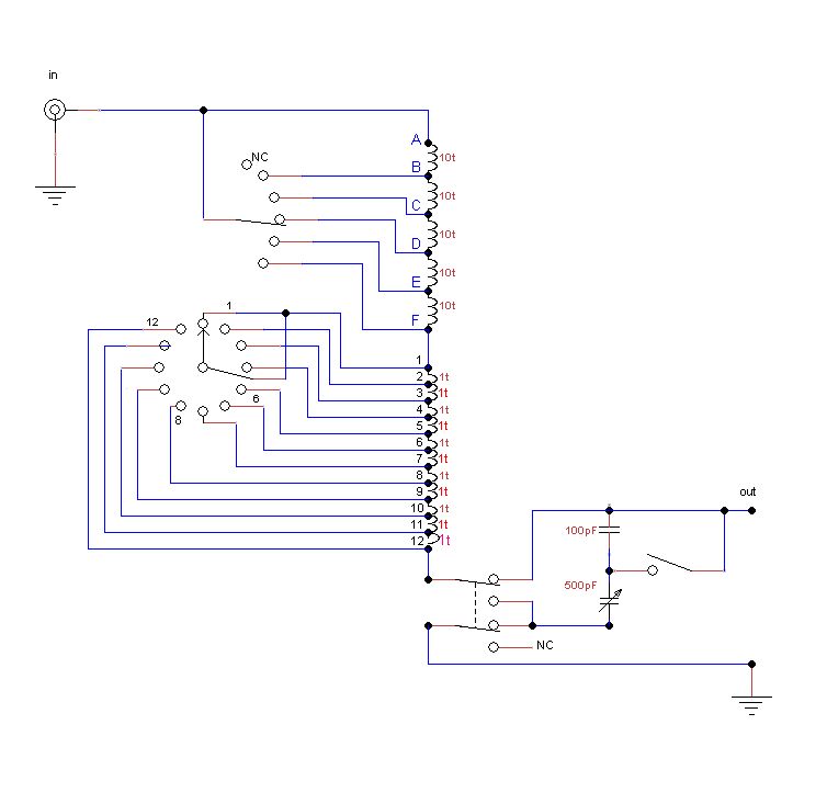
To match this simple aerial I used an L-match as shown. The majority of HF transceivers still have a type of pi-network as the bandpass output filter and I deemed it unnecessary to have an input capacitor in the matching unit.
The inductor started as an air-cored coil and progressed to a dust-cored toroid, probably a T200-2, and I may have cut an air gap as the inductance was excessive.A switch is included to convert to a series-match, plus padding capacitors.
One problem with using a single-ended aerial of random length lies with some of the high voltages present at the aerial output terminal and, by lack of attention, I found myself with arcing across between cables which didn’t do the transceiver output filter much good either.
The reactance on 80m changed abruptly about halfway along the band meaning making changes along most of the band.
Altering the aerial length might have helped but I wanted as much wire as possible in the air.
Over two
decades the amount of QRM has increased, particularly with
the advent of ADSL, so I eventually changed the inverted-L to a
horizontal delta loop and made an open-wire feeder for it.
The “legs” are about 48m and 42m with the end quite short at
28m.
The height is an average of 12m.
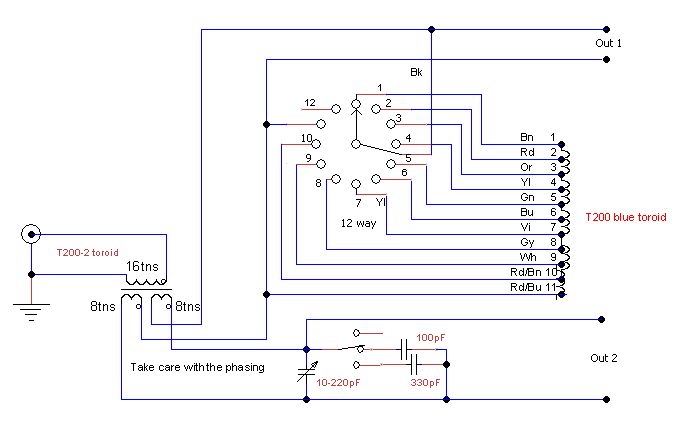
This obviously required a different matching device and, not wanting more than one variable capacitor, I found some ideas from PA0FRI on his websites for a compact unit which he named an “S-match” and Fig. 2 shows my version.
The tuning coil is a blue T200 of unknown naterial, it may even be a ferrite type for EMC use.Using a T200-2 orT200-6 might require a saw cut, easy with a dust core and a junior hacksaw.
The balun is a T200-2 wound with 1.5mm PVC insulated wire and the tuning inductor with 1mm enamelled wire.
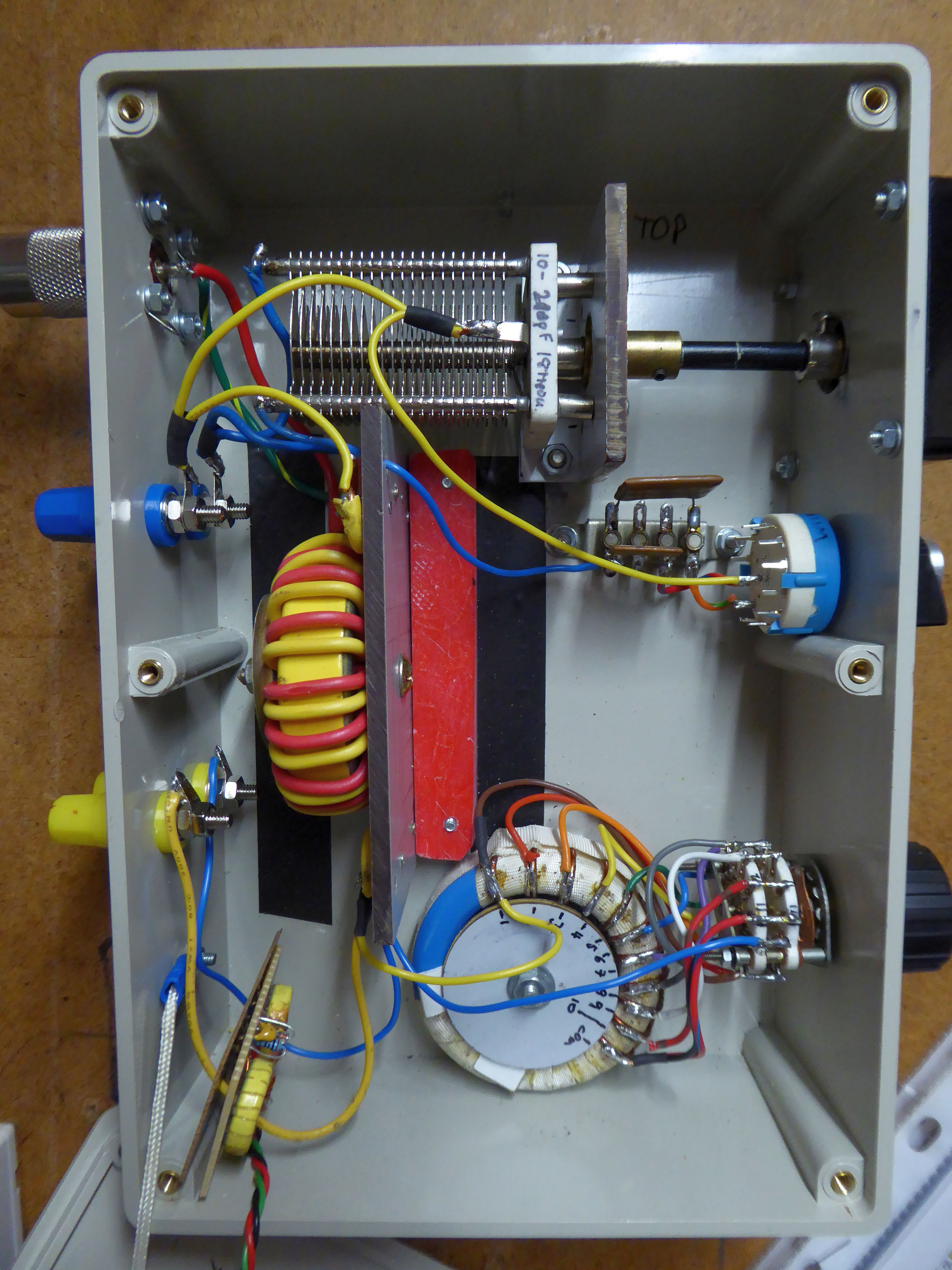
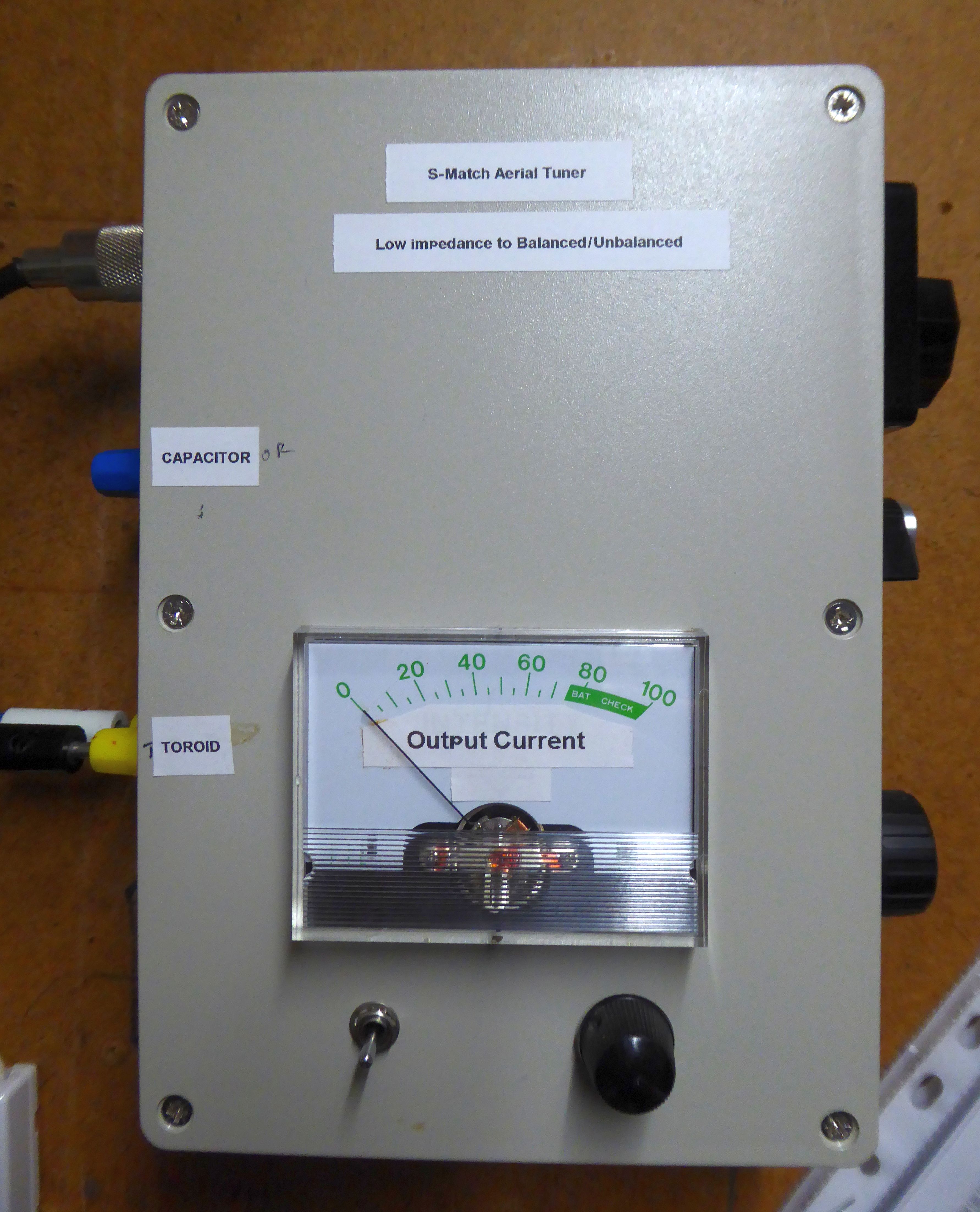
The general construction is shown in the other two pictures, the inductor switch is ceramic as there might be some high voltages present.The side panel has a reduction drive for the capacitor.Two pairs of output terminals are fitted so the aerial can be connected to the capacitor or the inductor.
I installed a small pair of toroids, with windings, over the output leads. A diode and filter provide a small voltage to give a comparative idea of output currents, The toroids are switched with a 2-way, centre-off, switch and a potentiometer for the meter.