The Mk 1 Antenna Tuner (With apologies to W Heath Robinson)
|
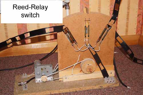
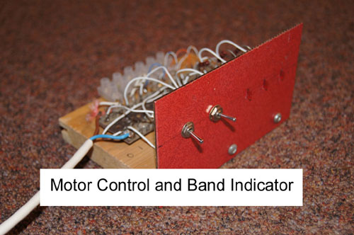
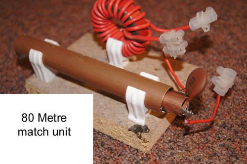
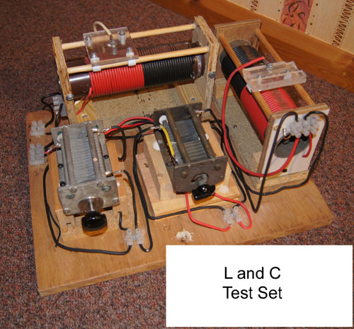
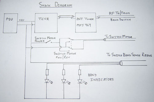
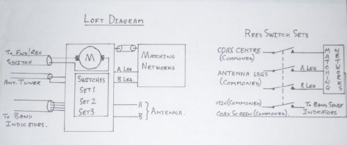
When I moved from my temporary ground-floor shack to a heated cabin in the loft of my garage, I accepted that a long-wire antenna was no longer practical due to the lack of an RF earth. I could have used a counterpoise system, but that would have required a lot of wire to be laid out. As a tower was out of the question, it came down to a trap dipole or a doublet. I went for a doublet, suspended from a pole taking the apex above the roof of the house. Keeping the ends out of reach of all but the most determined, I was still able to deploy about 38 metres of wire each side. The classical doublet has a balanced feed direct from the transmitter to the centre point of the radiator, and has to be kept away from structures, especially metal. The total length (feed plus radiator) can be arranged to match a number of amateur bands. For my application this was impossible, so the idea of a short balanced feed into the house loft to a matching device and then by coax to a mop-up tuner in the shack was tried. Reluctant to spend a lot on a remote auto-tuner for an idea that might not work, I devised the motor-driven switch in the photos. The motor had its own gearbox, and was controlled from the shack. The motor operated a magnet on a pivoted arm to operate a group of four reed switches for each band. The coax feed was commoned across the feed reeds, switched to the matching networks. The other side of the matching networks (A and B legs) were switched to a commoned feed to the antenna. The fourth reed was used to provide an indication in the shack of which matching network had been selected. This wasn’t totally fool-proof – a little adjustment was required to get all four reeds switched together. The spacing used between the reed sets was just about the minimum possible to operate a set of reeds while releasing all of the adjacent set. While setting up the matching networks, it was found that although the doublet was physically symmetrical, electrically it was anything but. Using a home-brew contraption of variable inductors and capacitors, and measuring with an MFJ Analyser, all sorts of combinations were used to get a reasonable match to 50 Ohms on the 80, 40 and 20 metre bands: 80 metres : Capacitance 145pF in ‘A’ leg, inductance 9.1 microhenry in ‘B’ leg 40 metres : Inductance of 15 microhenry in ‘A’ leg, through connection in ‘B’ leg 20 metres : Through connection in ‘A’ leg, Inductance of 0.8 microhenry in ‘B’ leg, with 37pF between ‘A’ and ‘B legs on the coax side of the network, and 135pF between the ‘A’ and ‘B’ legs on the antenna side. NB: The coax centre became the ‘A’ leg, and the screen became the ‘B’ leg. The coax was sleeved with a number of ferrite rings to ensure unbalanced operation and prevent radiation from the screen.
|
|
|
|
|
|
|
|
|
|