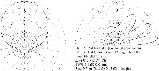
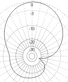
The field strength chart shows a normal horizontal Moxon field strength chart compared with the worst type of distortion, caused here with spacing between horizontally polarised Moxons at 90° to each other and 375mm apart. This 375mm is satisfactory for opposing polarities and for similar polarities facing in the same direction.
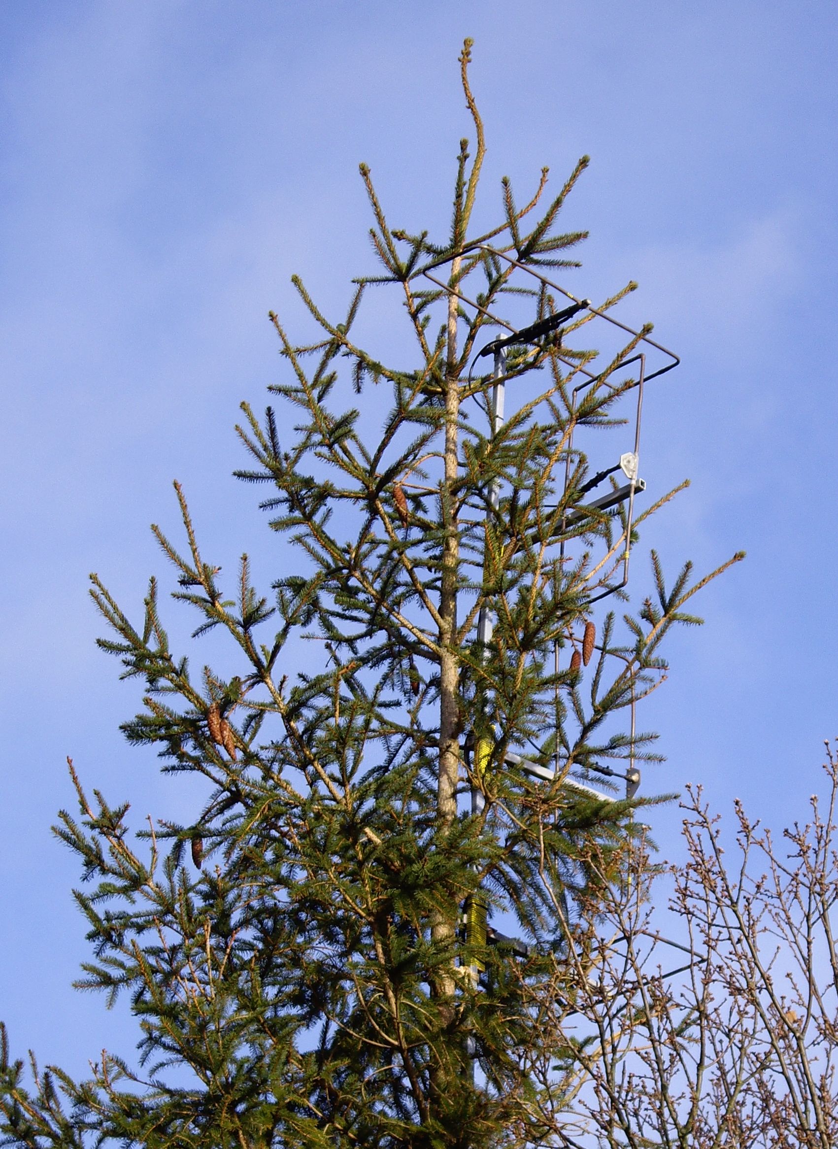
After becoming interested in some of the VHF contests it was deemed necessary to have both vertically and horizontally polarised aerials. Lacking a rotator and wishing to continue using the Christmas tree, I made four Moxon aerials from 10mm copper tube. The bamboo pole was replaced by a fibreglass, 25mm square-section tube from Engineered Composites in Chester. (Square-section implied that it would not turn round on the tree by itself). The Moxon has a better front to back ratio than the more simple Yagi arrays and a wider front lobe, some ± 40º compared to ± 32º for a 2- or 3-element Yagi. There were then, two aerials mounted facing North East and two facing South East, one of each pair being horizontal and one vertical. Spacing was not too critical, it made sense to have opposing polarities next to each other but I did model these with MMANA-GAL to confirm the minium spacing. Four cables were run down into the shack (75 ohm satellite cable again) and a 4-way switch made using an ordinary rotary switch in a diecast box with 5 sockets. Each fixed aerial has 3 ferrite sleeves on the coax close to the termination on the aerial itself.
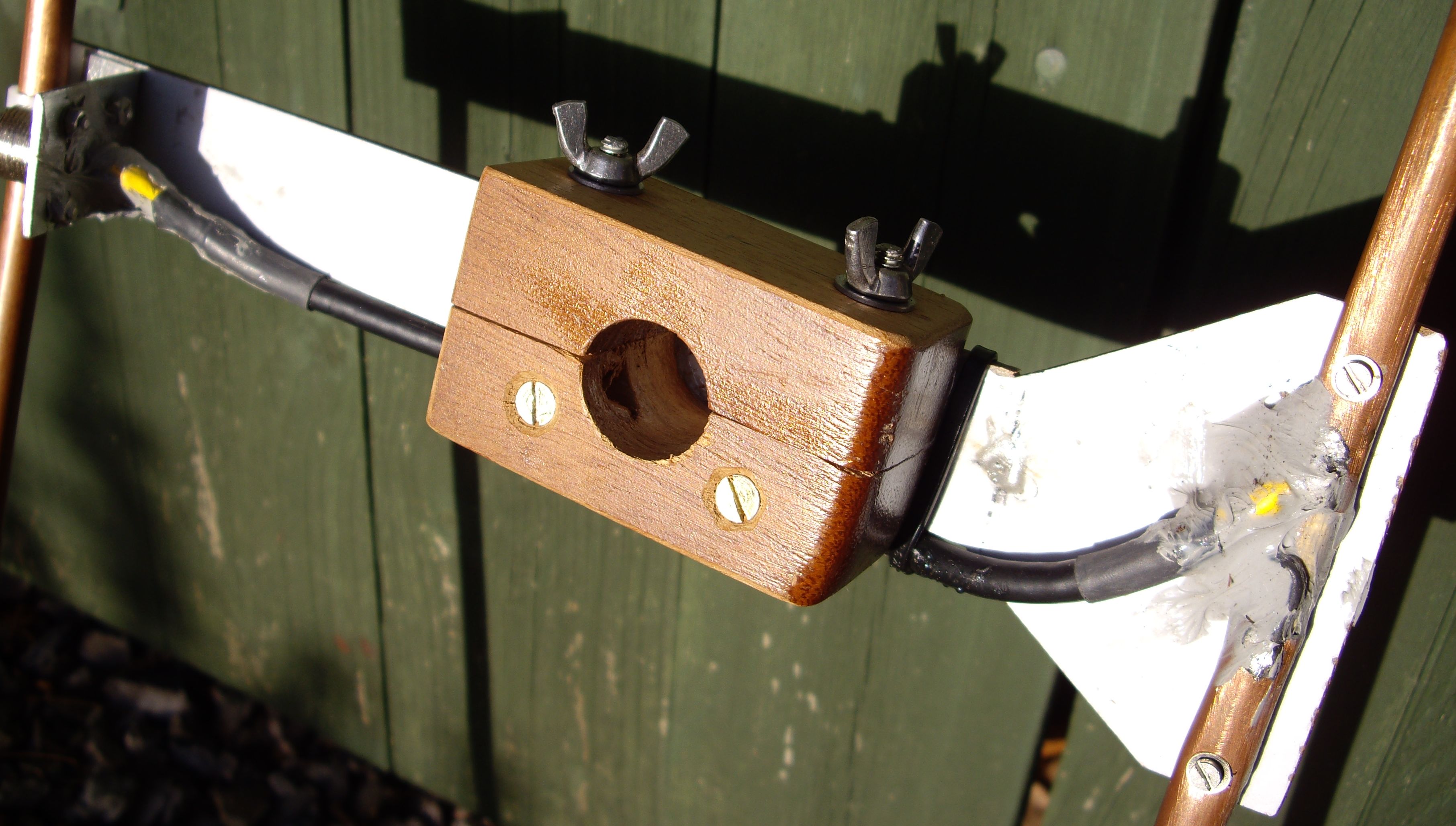
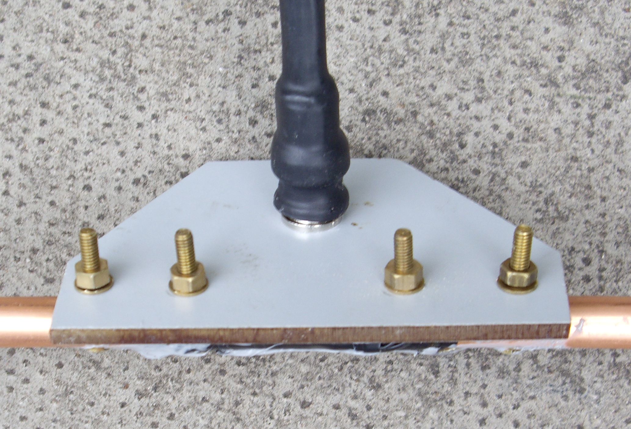
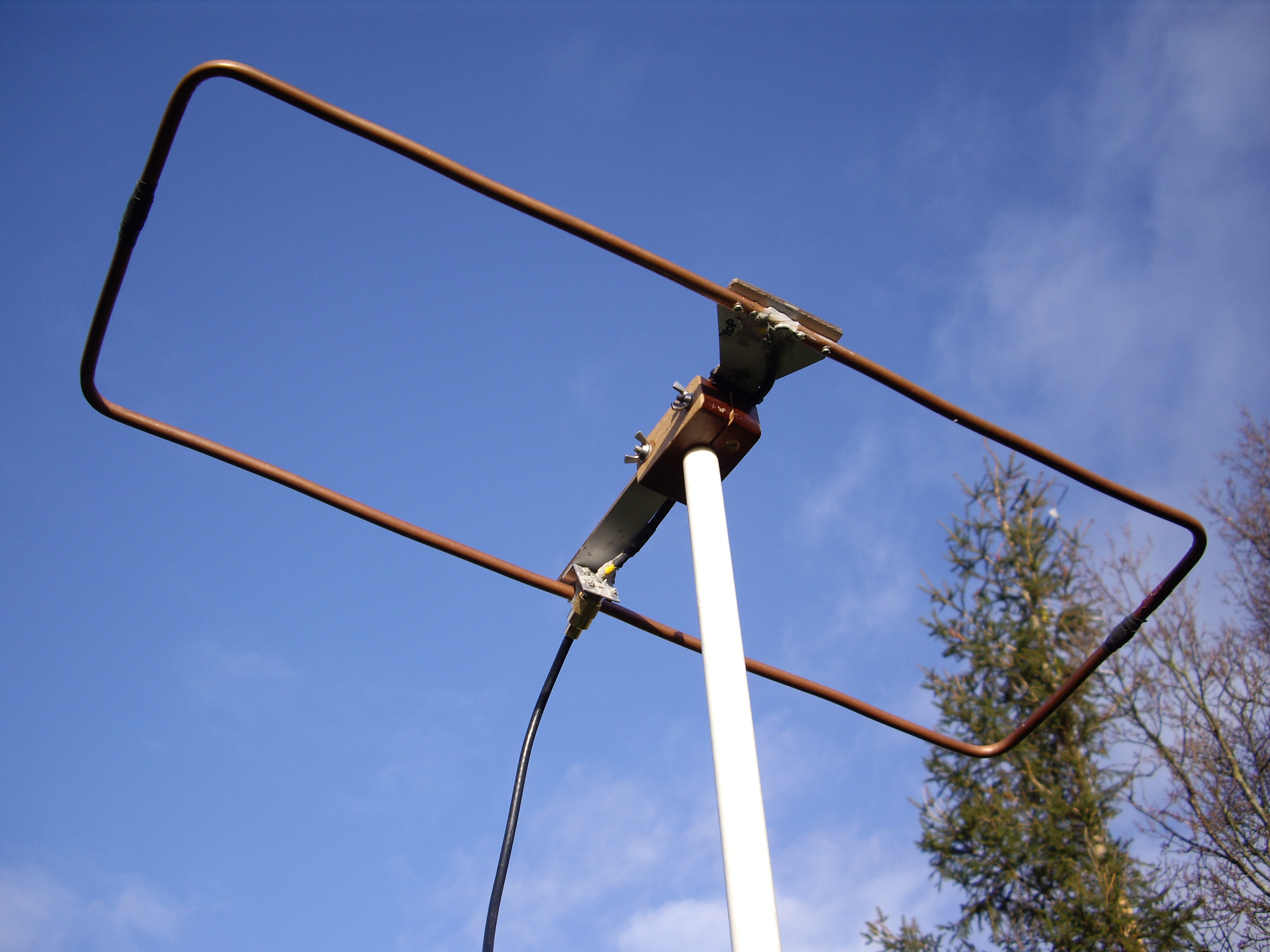
The portable Moxon was made in a similar way, it's very easy to carry uphill for SOTA or backpack contests. It has a split mahogany block with screw clamps to affix it to the 25mm fibreglass pole. The connector plate is SRBP with brass screws and all the joints are dowel with self-amalgamating tape or silicon sealant. This aerial, having been fallen on and sat on, being of annealed copper, it's also easy to straighten out again.